Injection mold design using Pro/E (Fig.)
Pro/ENGINEER is a CAD/CAM software produced by PTC Corporation of the United States. It is famous for its parametric design concept and brings great convenience to traditional mechanical design and manufacturing. The parametric design provided by Pro/ENGINEER has 3D solid modeling, a single database and features as the design unit, so the designer can calculate the volume, area, centroid, weight and moment of inertia of the product at any time. And regardless of the size modification on the 3D or 2D graphics, the associated 2D or 3D solid model and assembly, manufacturing, etc. are also automatically modified. Because Pro/ENGINEER introduces the concept of manufacturing in the design, the designer can make corrections such as adjustment, insertion, deletion, and redefinition of the features in a reasonable and non-violation order.
First, the design process
Typical Injection Mold Design Process In the Pro/ENGINEER environment, the injection mold design process consists of the following steps:
(1) Create a plastic part model (also known as three-dimensional modeling);
(2) Create a blank to define the volume of all mold components;
(3) The characteristics and dimensions of the cavity and core are constructed according to different shrinkage rates, draft angles and plastic parts models;
(4) adding mold assembly features to form a gating system, defining a parting surface and a module;
(5) Define the steps of opening the mold and check the interference;
(6) Assembling the mold base as needed to complete the cooling system design;
(7) Complete the part drawing of all parts;
(8) Generate the NC code of the part according to the processing needs.
Second, the mold cavity and core design
In the design process, firstly, by setting the shrinkage rate of different parts of the plastic part model, constructing the design model, generating the cavity and the core feature size, and then overlapping the design model with the cavity or core blank, after a series of faces The formation, extension and fusion operations form the parting surface, and finally the design model is excavated from the blank, and the cavity and the core are cut from the parting surface, as shown in Fig. 1, Fig. 2 and Fig. 3.
Figure 1 Plastic products
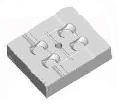
Figure 2 Die
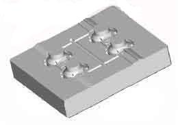
Figure 3 punch
The creation of parting surfaces is the most complex and critical part, where copying solid surfaces is a commonly used command. When copying the surface of a solid, try to use Copy→Surf&bnd to select the desired surface by selecting the seed surface and the boundary surface, instead of copying the surface using Copy→Indivsurfs, and then merging the surfaces into the desired surface. Because this is not only slow, but also easy to cause the surface to be lost, the solid surface cannot be completely selected.
The cavity or core produced by the above method is monolithic. In view of the manufacturing process, it is also possible to further decompose the cavity or core by the operation of the body to make the monolith into the insert.
After the mold design is completed, use the draft slope check function to check whether the mold is broken or not. If there is a reverse buckle, the piece cannot be demolded and must be modified.
Third, the processing of mold parts
Under the NC module of Pro/ENGINEER, according to the processing needs, NC code for CNC turning, CNC milling and WEDM can be generated. The specific process is shown in Figure 4.
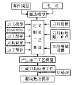
Figure 4 mold part processing flow
Fourth, other functions
Pro/ENGINEER has powerful interface functions, and can exchange data files with other CAD/CAE/CAM software through IGES, STL, SET, STEP and other formats. In the development of plastic products, this interface is usually connected with C-MOLD, MOLDFLOW, Z-MOLD and other software, and their analysis modules are used to analyze the shape in Pro/ENGINEER to determine the structure of the mold and the injection molding process.
Pro/ENGINEER's Pro/PROGRAM is an important tool for parts and assembly automation design. Users can control the presence or absence of part features, size and presence or absence of parts, and parts by a very simple high-level language. Easy display or full display and the number of parts. When the Pro/PROGRAM design of a part or assembly is completed, when the part or assembly is read, various changes can be obtained by interactively to obtain different geometric shapes to meet product design requirements.
Pro/ENGINEER also makes it easy to build parts libraries. The common parts and standard parts required in the design of the injection mold can be established according to the requirements of the user, and each pair of molds designed by the user can be used as an integral part of the mold library for subsequent mold design applications.
V. Conclusion
Pro/ENGINEER provides a design concept that combines design, manufacturing, assembly and production management to give a complete concept of “designâ€. Its powerful features, especially surface modeling and mold design capabilities, provide powerful tools for engineers and production managers to achieve high quality product development in the short term.
In addition, the introduction of parallel engineering technology into the mold design of Pro / ENGINEER, can be from the traditional mold design and manufacturing process route (ie mold structure design → mold cavity, core two-dimensional design → process preparation → mold cavity, type Core three-dimensional modeling→CNC machining instruction programming→CNC machining) is changed to a parallel route of design and process preparation by different engineers at the same time, which not only improves the manufacturing precision of the mold, but also shortens the design and numerical control programming time by more than 40%. The design engineer considers the molding process of the mold and the factors affecting the life of the mold when designing the three-dimensional parts of the product, and performs proofreading, inspection, and pre-discovering errors in the design process. After the initial establishment of the 3D model of the product, many engineers in the design, manufacturing and auxiliary analysis departments can simultaneously perform mold structure design, engineering drawing design, mold performance auxiliary analysis and programming of CNC machine tool machining instructions, and each engineer has Modifications made by the product are automatically reflected to other engineers, greatly reducing the time required for design and CNC programming. In addition, the single database and parametric solid feature modeling technology of Pro/ENGINEER software provides a reliable technical guarantee for parallel engineering.
Exposed Shower Sets,Universal Bathroom Shower Set,Shower Set For Bathroom,Hotel Shower Set
Kaiping Jenor Sanitary Ware Co., Ltd , https://www.sanitaryjenor.com