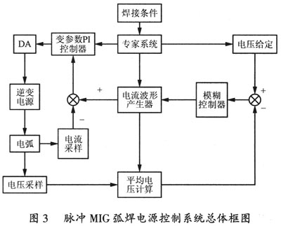
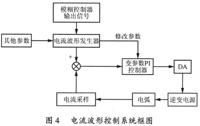
2 power control system design 2.1 Pulse MIG arc welding power control system overall plan The overall design of the pulsed MIG arc welding control system is the key to system design, which involves automation, computer and welding. The overall scheme of the power control system is shown in Figure 3. The pulse MIG arc welding power supply control system has three parts: current waveform control system, arc length control system and expert system. The current waveform control system and the arc length control system are closed-loop control systems, and the output of the arc length control system is the input of the current waveform control system, so the whole system is a double closed-loop control system, the current waveform is controlled as an inner loop, and the arc length control is Outer ring. The expert system is the regulating part of the entire double closed loop system. 2.2 Design of various parts of the control system 2.2.1 Current waveform control system In order to achieve the accuracy of current waveform control, the system should use PID control. Since the ideal differential control reacts faster to strong disturbances, the thermal inertia of the arc makes it impossible for the system to respond to differential control in time. In addition, the ideal differential control will amplify the noise interference in the deviation signal e(t), resulting in a large noise output, which affects system performance. Therefore, the system uses a variable parameter PI controller. For pulsed MIG welding, the transition pattern of one pulse and one drop is the best among the welding quality in all transition forms. At this time, the size of the droplet is equivalent to the diameter of the wire, so the control idea of ​​the droplet transition is to control the shape of the waveform. To ensure the same size of the droplets. Waveform control determines the behavior of a single droplet. In the cycle of droplet transfer, the transition of the droplet can be divided into six stages. In these stages, different proportional coefficients and integration time are used respectively to obtain better system dynamic response speed and base value. Steady-state accuracy of current time. The block diagram of the current waveform control system is shown in Figure 4. Previous Next Huzhou Dinuoju Wood Industry CO.,LTD. , https://www.dnjflooring.com