Horizontal Water Circulation Pump Horizontal Water Circulation Pump,Water Circulation Pump,Circulation Pump,Multistage Water Pump Shanghai NuoSai Pump Manufacturing Co., Ltd. , https://www.nuosai.net
1 Introduction
At present, in PCB assembly, surface mount components account for about 800/0, the cost is 60%, and the perforated components account for about 20%, and the cost is 40%. This type of hybrid plate can not be welded by the traditional reflow soldering technique, and two processes of reflow soldering and wave soldering are required. However, the wave soldering technology is applied to the soldering of the through-hole component (THD) printed board assembly. There are many disadvantages: it is not suitable for high-density, fine-pitch component soldering; bridging and leakage soldering; fluxing is required; The board is subject to large thermal shock and warp deformation.
In order to adapt to the development of surface assembly technology and solve the above welding difficulties, through-hole reflow soldering technology has been applied, and welding can be completed in one process. Through-hole reflow soldering (THR), also known as perforation reflow PIHR (Pin-in-HoleReflow). The technical principle is that after the printed board is finished, a special template with a plurality of needle tubes is used to adjust the position of the template to align the needle tube with the via pad of the interposing component, and the solder paste on the template is leaked using a doctor blade. On the pad, the plug-in component is then mounted, and finally the plug-in component and the patch component are simultaneously soldered by reflow soldering.
Through-hole reflow soldering can replace wave soldering in many ways to achieve soldering of the interposer components, especially in the processing of solder joints with high-density patch components (or wire-spacing SMD). The use of conventional wave soldering has been powerless, and through-hole reflow soldering can greatly improve soldering quality, which is enough to make up for the lack of expensive equipment. The emergence of through-hole reflow soldering is very helpful for enriching the welding method, increasing the assembly density of the circuit board (which can distribute high-density patch components on the soldering surface), improving the soldering quality, and reducing the process flow.
2 through hole reflow soldering (THR&PIP) process
Generally, components can be processed into surface mount components, but some special-shaped components, such as connectors, transformers, and shields, still need to be processed into plug-in components in order to meet mechanical strength and high current requirements. Through-hole plug-in components are available. Better solder joint mechanical strength.
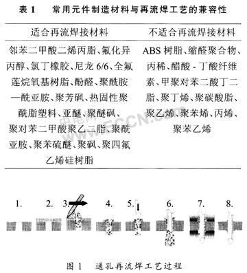
There are two problems to be considered when applying the plug component to the via reflow process: one is that not all the plug components can meet the requirements of the via reflow process, that is, the component material will not be destroyed by the reflow high temperature, 1 is a summary of component materials that can (not) be used in the reflow process; second, although through-hole connector components can be assembled using existing SMT equipment, they do not provide sufficient mechanical strength in many products, and On large-area PCBs, due to the flatness, it is difficult to make all the pins of the surface-mount connector have a firm contact with the pads. It is necessary to redesign the template, reflow temperature profile and pin and Opening diameter ratio, etc.
The main body of the through-hole component must be at least 0.5 mm away from the surface of the board to prevent the solder paste from moving before and after the component is inserted. The component pins should not be too long, usually 1.0 to 1.5 mm longer than the board surface. In addition, fasteners must not have too much bite force because surface mount devices typically only support a crimp force of 10 to 20 N.
The through-hole reflow process is very similar to the SMT process, that is, the solder paste is printed on the PCB via pad, the insert is placed, and the solder is reflowed. FIG. 1 is a schematic diagram of a single-sided through-hole reflow process. The process is the same for both single-sided and double-sided mixed boards. 
1 2 3 4 Next page
General knowledge of through-hole reflow soldering technology
General knowledge of through-hole reflow soldering technology: