smart light,Rgb Led Strip Lights,Smart Led Strip Lights,Color Changing Led Strip Lights Guangdong Smart Street Lighting Co., Ltd , https://www.fldlight.com 1. Analysis of the spiral lower knife

2. Application of spiral lower knife
Application of spiral lower knife in CNC milling machine
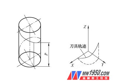
During the spiral lowering process, the tool travels along a spiral on a cylinder surface as shown in the drawing. When the tool is continuously running, the projection of the annular region formed by the rotation of the end edge on the bottom surface and the projection of the spiral on the bottom surface are a circle. During the machining process, when the spiral is under the knife, the tool path is cut along the spiral path with the change of the circumferential angle independent variable. When the depth Z reaches the preset depth, the spiral lower knife stops, where P is the pitch of the spiral line, ie The cutting distance of the tool in the Z direction for each cut of the tool in the XY plane.
Tool path map
(1) The traditional machining method for contour milling and milling of the cavity is to use the keyway milling cutter for groove cutting, while the end mill is more efficient when machining the cavity, but the vertical milling cutter is perpendicular to the lower knife to the cutter and The damage of the workpiece is obvious. In order to solve the problem of the end mill (or machine clamp) under the knife, the method commonly used in CNC machining has a spiral lower knife or a diagonal lower knife. When machining the inner cavity contour, especially the processing of difficult materials, during programming The method of spirally descending obliquely inserting the knife along the contour of the inner cavity can be used, which can effectively improve the processing efficiency and prolong the service life of the tool.
(2) Thread milling Traditional threading methods mainly use thread turning tools to turn threads or use taps, die manual tapping and buckles. With the development of CNC machining technology, especially the emergence of three-axis CNC machining system, CNC milling of more advanced threading thread is realized. Compared with traditional thread processing, thread milling has great advantages in machining accuracy and machining efficiency, and is not limited by the thread structure and thread rotation during machining. For example, a thread milling cutter can process a variety of different directions. Internal and external threads. For the thread that does not allow the transition buckle or the undercut structure, the traditional turning method or taps and die are difficult to machine, but it is very easy to implement by CNC milling. Moreover, in the process of CNC milling thread, the adjustment of the thread diameter size is very convenient, which is difficult to achieve by using taps and die. For example, to machine an internal thread of M40×1.5, the machining of the lower end of the machining center is programmed as follows:
%1
N1 G54 G90 X10.5 Y0 Z50 S500 M03 (establishing coordinate system)
N2 Z6 .M08 (feeding lower knife position)
N3 #1=0 (number of pitches)
N4 #2=1.5 (pitch value)
N5 #3=30 (threaded hole depth)
N6 #4=0 (milling pitch depth)
N7 WHILE [#4 LT #3] D01 (Judge thread milling depth)
N8 #1=#1+1 (calculation of pitch number)
N9 #4=#1*#2 (Calculate the milling pitch depth)
N10 G02 I-10.5 Z [-#2] F100 (spiral milling thread)
N11 END1
N12 G0 X0
N13 G0 Z100.
N14 M30
(3) Hole machining The spiral milling process is a combination of the "rotation" of the spindle and the "revolution" of the spindle around the center of the hole. This special motion mode determines the advantages of the spiral milling hole. First of all, the spiral milling hole has the advantages of smooth cutting process, small cutting force and one-time machining to meet the accuracy requirement. The trajectory of the tool center is a spiral rather than a straight line, that is, the tool center no longer coincides with the center of the hole being machined. It is an eccentric machining process. Only one tool can process holes of different diameters and high quality, which reduces the tool change time, saves the finishing process, improves the work efficiency, and reduces the number and types of tool magazine tools. Processing costs. Secondly, the spiral milling process is an interrupted milling process that facilitates the heat dissipation of the tool, thereby reducing the risk of tool wear due to temperature rise.
Hole machining adopts spiral feed G02/G03, format: G02(G03)XYIJZFL where L is the number of spiral coils. For example, a hole with a diameter of 50 is machined with a keyway cutter with a diameter of 10 mm, and the workpiece is 10 mm high. The programming is as follows:
%2
N1 G54 X0 Y0 Z30 M03S1000 (establishing coordinate system)
N2 G01 Z1 X20 F200 (feeding lower knife position)
N3 G91 G03 I-20 Z-1 L11 (roughing to spiral depth position 1 mm)
N4 G03 I-20 (finishing contour)
N5 G90 G01 X0
N6 G0 Z30
N7 M30