Wiring method, function setting and other parameters Gabion,Gabion Baskets,Gabion Box,Gabion Mesh Hebei Aibuer trading co., Ltd , https://www.ablehardwares.com
200W/400W three-phase motor driver instruction manual
1 Introduction
In order to fully utilize the functions of the inverter and ensure the safety of the user, please read this operation manual in detail. If you find any abnormality during use and this operation manual does not list this situation, please contact the regional distributors or Our business staff, we will solve product problems for you in time.
1.1. Display interface description:
L1: POWER indicator, power indicator, constant.
L2: Forward rotation indicator green (FWD), always on during operation. LED flashes when forward rotation stops.
L3: Reverse indicator light blue (REV), always on during operation. LED flashes when reverse rotation stops.
L4: Four digits display, when the highest digit is 0, it means button speed adjustment (potentiometer speed control failure); when the highest position is P, it means potentiometer speed adjustment (key speed regulation failure). And fault code display.
1.2. Button function explanation:
K1: Speed ​​reduction minus button/data setting minus (↓).
K7: Speed ​​plus button / data setting plus (↑).
K2: Forward/reverse switching button (FWD/REV).
K3: Save/Lock button (SAVE/LOCK).
K4: Start/stop button/data setting confirmation button (RUN/STOP/OK).
K5: Set the enter key (MENU/ESC).
K6: Function parameter display button (PK/SHIFT).
Potentiometer: Knob speed potentiometer.
2. Function description
2.1. Brief description of the inverter
The inverter is a single-phase voltage input and drives a three-phase motor. The frequency output is 1.0--100.0HZ. In order to increase the output voltage, this product uses SVPWM modulation mode, carrier frequency is 8.0KHZ. Suitable for 200W/400W motor, maximum output. The power is 300W/550W. The inverter can arbitrarily change the V/F curve by setting the V/F compensation frequency and setting the voltage ratio at this frequency. By setting the highest value of the V/F curve, according to the load situation Maximize the use efficiency of electric energy, reduce the heat of the motor, and extend the service life of the motor and the inverter.
2.2. Internal parameter setting
2.2.1. Description of the operation interface
The function parameters are displayed as follows:
1.t-xx: Displayed as the heat sink temperature value.
2.Cx.xx: Displayed as current current value.
3.xxx.x: Displayed as DC bus voltage value.
4.xxxx is displayed as the motor speed.
5.Fxx.x: Displayed as the running frequency value.
6. Ex.x: indicates the fault, and the fault code is used to determine the cause of the fault.
7. The power indicator flashes to indicate that the machine and the external RS485 communication are successful.
8. Run indicator FWD (green) LED, REV (blue) LED, flashing means stop; steady light means running in this mode.
External terminal control chart:
serial number
representative
Features
1
↔↔↔
D1
2
↔↔↔
D2
3
↔↔↔
RS485+
4
↔↔↔
RS485-
5
↔↔↔
M2/D3
6
↔↔↔
MI
7
↔↔↔
MO
8
↔↔↔
GND
9
↔↔↔
VR (potentiometer)
10
↔↔↔
+5V
Note :D on behalf of the period of speed
Serial number
D3
D2
D1
1
1
1
1
2
1
1
0
3
1
0
1
4
1
0
0
5
0
1
1
6
0
1
0
7
0
0
1
8
0
0
0
Note: M1, M2, D1, D2, D3 are high when nothing is connected, so the low level is valid, and D1, D2, and D3 are all high level to indicate the lowest speed.
The segment speed map is as follows:
External terminal control wiring diagram:
2.2.2. Setting interface description
When the MENU button is pressed, the screen displays flashing -0.0- by the data setting plus or minus button (↑) (↓), adjust the setting options to be entered. The setting options are shown in Table 1. The data can be passed in the setting options. Set the shift key (PK/SHIFT) and the data setting plus or minus button (↑) (↓) to adjust the data to be set. Press the data setting confirmation key (RUN/STOP/OK) to return to the main menu display flashing - XX-; According to this method, the next option can be set. When all the setting options are completed, press the data setting save button (SAVE) to display the flashing SAVE, and then press the data setting save button (SAVE). The changed data is saved in the internal EEPROM. Start the inverter and run according to the set data. It does not need to be powered off to start up at power-on. When you don't want to save the data, you can press the menu setting to exit the key (MENU/ESC) to exit without affecting the previous time. The set parameters, or 20S without key operation, will automatically return to the running interface.
Table 1
Serial number
Setting code
content
Description
Factory value
1
-0.1-
Set startup time
1. Set the number 01 to represent 5S
1
2. Set the number 02 to represent 2.5S
3. Set the number 03 to represent 1.6S
4. Set the number 04 to represent 1.0S
2
-0.2-
3
-0.3-
Minimum frequency compensation
Setting range: 5-15
8
4
-0.4-
Set the maximum frequency of compensation
Setting range: 5.0-30.0HZ
20.0
5
-0.5-
Set the compensation maximum frequency to voltage ratio
Setting range: 25-85
55
6
-0.6-
Maximum frequency limit voltage ratio
Setting range: 80-128
128
7
-0.7-
RS485 baud rate (Baud rate of RS485)
0,48(4800) 1,96(9600) 2,192(19200) 3,384(38400)
96
8
-0.8-
RS485 format, ASCII (ASCII format of RS485)
1,8N1 2,8N2 3,8E1 4,801
8N1
9
-0.9-
Machine number
1 to 255
1
10
-1.0-
Input of frequency
0, panel keyboard control (Panel keyboard) 1, panel potentiometer control (panel potentiometer control) 2, external analog signal input (output voltage is 0-5V) or external potentiometer (The external analog signal input (output voltage of 0- 5V) or external potentiometer) 3, RS485 (RS485) 4, segment speed input
1
11
-1.1-
Start/Stop Control Source (Control of Run/Stop)
0, Panel keyboard control 1, RS485 (RS485) 2, forward and forward (Forward) 3, power on or reverse (Reverse) 4, external port (External port)
0
12
-1.2-
Parking Mode (Stop Mode)
0, Inertia 1, Free gear 2, Braking value
1
13
-1.3-
MI function selection (Function selection of MI)
0, MI1 forward/stop, MI2 reverse/stop; (M1FWD/Stop, MI2REV/Stop) 1, MI1 run/stop, MI2 reverse/forward rotation; (MI1FWD/Stop, MI2REV/FWD) 2, MI1 operation / stop, MI2 speed (MI1FWD/Stop, MI2 Speed)
0
14
-1.4-
M0 function selection (Function selection of M0)
0, Operrating instruction 1, Set arrival instructions 2, Fault indication 3, undefined (customizable)
0
15
-1.5-
Overload protection selection
Undefined
16
-1.6-
Over temperature protection selection
30 ° C ~ 85 ° C
70 ° C
17
-1.7-
Maximum frequency setting
1.0 to 99.0 Hz
50.0
18
-1.8-
Minimum operating frequency
1.0 to 30.0 Hz
1.0
19
-1.9-
working frequency
1.0 to 99.0 Hz
50.0
20
-2.0-
Output the highest voltage corresponding frequency
35.0 to 99.0 Hz
50.0
twenty one
-2.1-
Segment 1 setting (Speed ​​1 set)
1.0 to 99.0 Hz
5.0
twenty two
-2.2-
Speed ​​2 set (Speed ​​2 set)
1.0 to 99.0 Hz
10.0
twenty three
-2.3-
Speed ​​3 set (Speed ​​3 set)
1.0 to 99.0 Hz
20.0
twenty four
-2.4-
Speed ​​4 set (Speed ​​4 set)
1.0 to 99.0 Hz
25.0
25
-2.5-
Speed ​​5 set (Speed ​​5 set)
1.0 to 99.0 Hz
35.0
26
-2.6-
Speed ​​6 set (Speed ​​6 set)
1.0 to 99.0 Hz
40.0
27
-2.7-
Speed ​​7 set (Speed ​​7 set)
1.0 to 99.0 Hz
45.0
28
-2.8-
Operation frequency
1.0 to 99.0 Hz
45.0
29
-2.9-
Undefined (customizable)
----
---
30
-3.0-
Current display options
1: percentage
1
31
-3.1-
Undefined (customizable)
----
---
32
-3.2-
Undefined (customizable)
----
---
33
-3.3-
Braking time
Undefined
34
-3.4-
Brake coefficient
Undefined
35
-3.5-
Number of pole pairs
1 to 6
2
36
-3.6-
Motor slip
0.01 to 1.00
1.00
37
-3.7-
Motor rated speed (Motor rated speed)
1~9999
1500
38
-9.1-
Restore default value
Display flashing CLE, press OK to perform the operation.
39
-9.7-
Hardware version number
-X.xx
40
-9.8-
Software version number
-X.xx
2.2.3. Low frequency V/F compensation instructions
According to the load condition, the value of Table 2 and the linear V/F curve value, you can set the value of -0.3-, -0.4-, -0.5-. If you want to increase the motor torque at low frequency, you need to select the upper limit frequency of the lifting torque. 0.3-, -0.4- set the maximum frequency-to-voltage ratio. The corresponding frequency or similar frequency can be found in Table 2. When it is higher than this data, the slope of the V/F curve will be increased and the torque will be increased. When the data is lower than the data. Will reduce the slope of the V / F curve, reduce the torque.
For example, the value is set to 20.0 in -0.3-, the value is set to 60, 55, 30, and -0.5 in -0.4-. The default setting is 8. V/F is as follows:
2.2.3. Maximum frequency limit voltage ratio
When the load is relatively small, when the motor is running at the highest speed, the optimal operation can be achieved by reducing the option data set by -0.6.
Table 2: Linear voltage ratio
Frequency / HZ
Voltage ratio
Frequency / HZ
Voltage ratio
Frequency / HZ
Voltage ratio
Frequency / HZ
Voltage ratio
Frequency / HZ
Voltage ratio
1
8
11
32
twenty one
57
31
81
41
106
2
10
12
35
twenty two
59
32
84
42
108
3
13
13
37
twenty three
62
33
86
43
111
4
15
14
40
twenty four
64
34
89
44
113
5
18
15
42
25
67
35
91
45
116
6
20
16
45
26
69
36
94
46
118
7
twenty three
17
47
27
72
37
96
47
121
8
25
18
50
28
74
38
99
48
123
9
28
19
52
29
77
39
101
49
126
10
30
20
55
30
79
40
104
50
128
2.2.4. Voltage ratio and voltage output relationship
Output voltage = power supply voltage * (voltage ratio) / 128;
3. Set the case
Case 1: Setting the motor acceleration time
Turn on the power, press the (MENU/ESC) button to enter the main menu to display -0.0-, press the (↑) button to display -0.1-, press the (RUN/STOP) button to display 01.01: the acceleration time is 5S; 02 represents The acceleration time is 2.5S; 03 means the acceleration time is 1.6S. Use the (↑) key, and the (↓) key to select the acceleration time to be adjusted. Press the (RUN/STOP) key to return to the main menu -0.1- Continue to set other options. If you do not set other options, press (SAVE/LOCK) to enter the save option. The digital tube displays the flashing SAVE. Press the (SAVE/LOCK) button again to return to the frequency display interface. If you do not want to save, press (MENU/ESC). ), the previously modified data is invalid.
Case 2: System Restore Factory Defaults
Press the (MENU/ESC) button to enter the main menu to display -0.0-, press the (↑) button to display -0.1-, press the (PK/SHIFT) shift button to adjust the main menu -x.1-to-9.1-, Press the (RUN/STOP) button to display the flashing CLE. Press the (RUN/STOP) button to restore the factory default value and return to the frequency display interface. If you do not want to operate, press the (MENU/ESC) button to return to the frequency display interface.
note:
1. Press (MENU/ESC) in any setting interface to return to the frequency display interface.
2. During the save, the digital tube displays the flashing SAVE, press (MENU/ESC) to exit the save. The previously modified data is invalid, and the parameters will automatically reply to the previous parameters.
3. When the data is adjusted, you can use the (PK/SHIFT) button to quickly set the parameters of the digital tube.
4. All the places where you need to save data need to press the SAVE/LOCK button twice to prevent misoperation.
4. Fault code
When the inverter is faulty, the four digits will flash and display: Ex.x
The fault code and its solution are as follows:
Serial number
error code
content
Abnormal
Remarks
1
E-0.1
Inverter overheating
1. Detecting line faults
2. The surrounding temperature is too hot or poorly ventilated
1. Inverter repair
2. Improve ventilation
2
E-0.2
Pulse overcurrent
Too much load
2. Improper setting of V/F mode
3. Detecting inverter failure
1. Inverter repair
2. Set the appropriate V/F curve
3
E-0.3
4
E-0.4
Inverter overload
Too much load
2. Improper setting of V/F mode
1. Increase the inverter capacity
2. Set the appropriate V/F curve
5
E-0.5
6
E-0.6
Temperature sensor failure
Temperature sensor is open or damaged
1. Check the temperature sensor connection
2. Inverter repair
7
E-0.7
Temperature sensor failure
Short circuit or damage to temperature
1. Check the temperature sensor connection
2. Inverter repair
8
E-0.8
Inverter overload 100%
Inverter output power exceeds 100% for more than 6 seconds
1. Replace the higher power inverter
5. Notes
1). When the fault code is displayed as E-0.2, you need to pay attention to the following points:
1>. The load is too heavy, the acceleration time is too short, adjust the acceleration time, replace the higher power inverter.
2>. The motor rated power is too large, replace the motor with the inverter.
The parameter setting in 3>.-0.3-, -0.4-, -0.5-, -0.6- is unreasonable. It is recommended to restore the factory value.
2). When the motor is running, it will generate strong interference. At this time, the manual adjustment of the frequency may fail. However, you can still adjust the frequency by pressing and holding the button. It is recommended to use a single button or stop the motor. Change the frequency down.
3). It is recommended to use the button speed regulation during precise speed regulation. The potentiometer speed regulation will produce a slight offset in the motor running or installation system vibration to affect the control accuracy.
4). When the ambient temperature is too high, it is necessary to leave enough heat dissipation space.
6. Use environment
Power supply: single phase AC220V ± 20%
Temperature: -10 ° C ~ 55 ° C
Humidity: 0% ~ 65%
5.2.1. Maintenance and peripheral components
5.2.1.1. Maintenance inspection
The inverter does not require frequent inspections. Maintenance
In order to maintain good operating characteristics for a long time, please check regularly according to the following points. When checking, be sure to turn off the power, and wait until the power indicator is off before starting, because the internal bulk capacitor will have residual voltage.
(1) sweeping the internal unclean accumulation
(2) Check the terminal screws and the part fixing screws for looseness. Loosen the screws to lock them.
(3) Pressure insulation test
(a) When performing the insulation withstand voltage test of the external circuit, it is necessary to remove all the wires connected to the external drive from the external circuit.
(b) When testing the insulation withstand voltage inside the inverter, only test the main circuit of the inverter, and use the DC file during the test.
500V high resistance meter insulation resistance must be above 100MΩ.
Shanghai Futz Electromechanical "target=_blank> Electromechanical Technology Co., Ltd.
Manufacturer technical consultation
2014, 07, 09
Http://news.chinawj.com.cn 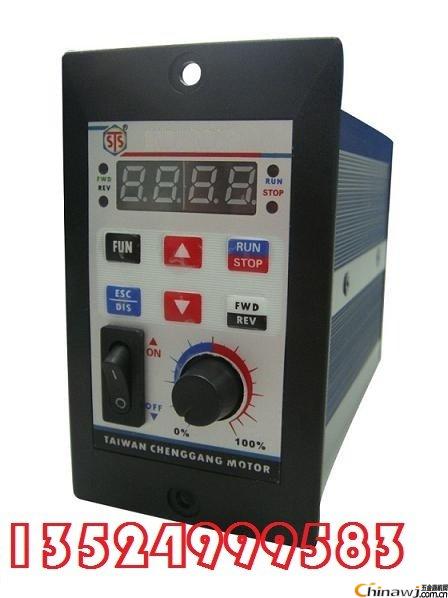 Editor: (Hardware Business Network Information Center) http://news.chinawj.com.cn